- EU Law: Dominant Undertakings & EU Four Freedoms – Legal Implications and Market Impact
- BTEC Level 3 Unit 19 Analogue Electronic Devices and Circuits, Assignment 2
- OTHM Level 5 Unit 2 T/650/1139 Managing the Safeguarding and Protection of Vulnerable Individuals
- Legal Analysis of Negligence Claim Against SamsTech for AI Chatbot Errors
- FINA 1007 Research Methods: Assessment Guide & FAQs
- Mathematical Methods in Physics Assignment Question
- Unit 5048 J/650/2990 Sensors and Automation BTEC Level 5
- Transport for London (TfL) Cycle Data Analysis Project – Programming & Data Science
- Sport Coaching Portfolio: Safe, Ethical, and Effective Practices – Assessment 2
- K/507/1406 HSC CM1 Unit 1 Equality, diversity and rights in health and social care, NCFE CACHE Level 3
- MS420/MS508 Advancing Sustainable Development Goals (SDGs) through Business Practices
- C1808 Unit 500 Understanding Leadership and Management in Adult Care – Theories, Styles & Best Practices
- Level 5 Leadership and Management in Adult Care Unit 17, Unit 18 & Unit 16
- Donald Trump’s Statement on South Africa: Economic and Health Impacts
- Level 3 Certificate in Assessing Vocational Achievement (CAVA)
- H/615/1488 Unit 4014: Production Engineering for Manufacture, BTEC Level 4
- CIPD Level 7CO02 People Management: Strategy, Engagement & Technology
- Unit 6: HND Construction Management – Architectural Design and CAD Standards
- Unconscious Bias and Equal Opportunities in the Workplace
- Understand Safeguarding: Sources, Whistleblowing, Accountability & Information Sharing
Wind tunnel testing plays an important role in the design of aircraft. It provides a check on the accuracy of the initial design: Aerospace Engineering, Coursework, UOL, UK
| University | University of Liverpool (UOL) |
| Subject | Aerospace Engineering |
AP: AIRCRAFT PERFORMANCE – LIFT DRAG AND PITCHING MOMENT CHARACTERISTICS
Introduction
Wind tunnel testing plays an important role in the design of aircraft. It provides a check on the accuracy of the initial design and can indicate ways to improve the aircraft characteristics. Amongst the most basic properties of interest to aircraft designers are the lift and drag characteristics. Knowledge of these enables many performance estimates to be made. The wind tunnel provides the means of estimating these characteristics, using a scaled down model.
Testing should ideally be carried out at Reynolds Numbers close to the projected full-scale values. However, this is rarely achieved in practice, except in the largest of tunnels – working sections of order 4m x 3m – running at speeds in excess of 100 m s -1 . In this laboratory, limitations imposed by the wind tunnel size and operating speed give rise to Reynolds Numbers (based on the mean chord of the wing)that are around two orders of magnitude smaller than full-scale. One consequence of testing an aeroplane model at a small Reynolds Number is the occurrence of regions of flow separation at relatively small angles of incidence. Such laminar flow separations would not occur at full scale Reynolds numbers. One way to make the tests more representative is to roughen the surface just upstream of separation to make the flow turbulent. NB this has not been done on the current (very expensive!) models.
Aims and Objectives
The aim is to introduce you to the basics of wind-tunnel testing and data processing, and to the use of the associated equipment (wind tunnel, balance, barometer etc.). The main objectives are
1. To record, process and present lift, drag and pitching moment data recorded over a range of AoA at constant air speed U.
2. To estimate several key performance-related parameters, including the lift-curve slope, the maximum lift coefficient and the drag polar for the model aircraft.
Apparatus
The tests are carried out using the AF100 open-circuit suction wind-tunnel and associated AFA3 three-component balance. The tunnel’s working section has a cross-section of 305mm x 305mm and length 600mm. The maximum air speed is 36 m/s.
A commercial wind tunnel model aeroplane will be mounted in the tunnel for you. It is mounted upside down in the working section, fixed on a rigid spindle coincident with the ¼ chord point. The spindle is gripped tightly in the balance. The model’s angle of attack can be adjusted and recorded using a protractor that forms part of the balance. An encoder also records the angle. The model is entirely supported by the balance; therefore, all aerodynamic and gravitational forces and moments acting on it are resisted by the balance. Even when there is no air flow, gravitational loads will be present. Since it is the aerodynamic loads we are investigating, we “zero” the balance with the tunnel fan motor switched off before each test, to remove the gravitational load offsets from the readings.
After “zeroing”, the balance gives measurements of the aerodynamic loads L, D and M.
More information about the operation of the balance can be found in [2].
Do You Need Assignment of This Question
Theory
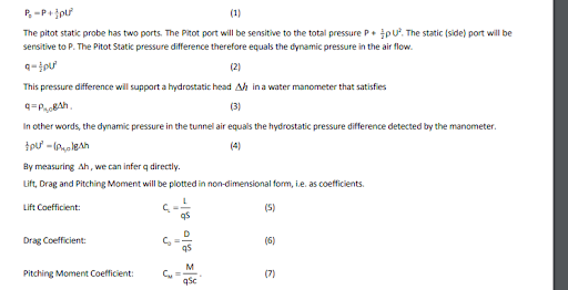
The tunnel is designed to produce a reasonably uniform flow across the working section. The flow speed can be controlled by varying the power to the drive motor. Upstream of the model is located a pitot-static tube which will be used to provide dynamic pressure (q) measurements during the tests. The pitot-static is connected to the left-hand manometer marked 1 p . (Downstream there is a pitot probe which, together with a side-wall tapping, is connected to the right-hand manometer. We shall not use the downstream measurements during these tests.)
The tunnel draws stationary air (U0=0) in from the surrounds where the static pressure is P0, the barometric pressure. The air accelerates in the inlet so that in the working section the speed is U and the static pressure P. Neglecting losses in the inlet, Bernoulli’s equation tells us that
References
[1] Russell, J.B. (1996). Performance and Stability of Aircraft. Arnold, London
[2] Anonymous (2004). AFA3 The Component balance User Guide. TQ Educational Training Ltd Document Reference
DB/MB/AD/09/04
[3] Anonymous (2012) VDAS Versatile Data Acquisition System User Guide. TQ Educational Training Ltd Document Reference
DB/12/12
[4] Walker, DJ (2017). Note on “Least Squares Fit for AP Lab. University of Liverpool. (See Appendix)
Are You Looking for Answer of This Assignment or Essay
Struggling with your Aerospace Engineering coursework? Our assignment help UK service is ready to assist! UK students can pay for aerospace engineering assignment help and get expert coursework writing help tailored to their needs. We deliver affordable, high-quality services, with 100% human-written assignments—no AI—ensuring A+ guaranteed results, on-time delivery, and plagiarism-free content. Let our professionals help you succeed in your Aerospace Engineering studies today!
Answer