- HSC Level 2/3 Unit 012 Assignment: Care Worker Responsibilities and Ways of Working
- CIPD Level 5HR03 Assignment: Understanding Reward Approaches and Their Impact on Performance and Contribution
- CIPD level 5HR02 Assignment: Talent Management and Workforce Planning Unit Guide
- Level 3 D/615/3823 Assignment: Regulation, Protection, and Collaborative Practice in Health and Social Care
- PGM216D Assignment: Bicycle Store Sales Management Application
- MATH6033 Assignment: Epidemiological Investigation of Cardiovascular Health and Tea Consumption Risks
- EH6147 Assingment: Stakeholder Analysis for Quality Improvement in Hand Hygiene Compliance
- Assignment: Investigation of Solution Concentration Through Standard Preparation, Titration, and Colorimetry Techniques
- MATH6033 Assignment: Cardiovascular Risk and Tea Drinking: Epidemiological Analyses
- CIPD level 3 3CO03 Assignment: Core behaviours for people professionals
- DAC4B1: Personal development in adult care settings
- Unit 19 Research Project Assignment 1: Impact of Corporate Social Responsibility on Business Success & Community Wellness
- EG5022 Assignment: Georeferencing and Accuracy Assessment of a Quarry 3D Model Using Photogrammetric GCPs
- Assignment: Financial Performance and Strategic Analysis of a UK Listed Company: A CORE Evaluation and Reflective Review
- 5CNMN002W Assignment: Advanced measurement- Major measurement taking off
- K/650/2298 Level 3 Understanding Roles, Responsibilities, and Effective Partnerships in Health and Social Care
- Understanding Information and Knowledge Management in the Workplace: A Briefing for HR Professionals
- HRM7010D Strategic Use of People Analytics in Enhancing Organisational Value and Agility
- TOWN1060 Urban Planning in the UK History Sustainable Design and Future City Development
- OTHM Level 5: J/650/1143 Research Methods in Health and Social Care
BTEC Level 4 Unit 19 – Analysis of electrical circuits with constant voltage/current sources: Electrical and Electronic Principles, Assignment 1, UK
| Subject | BTEC Level 4 Unit 19 - Electrical and Electronic Principles Assignment 1 |
Assignment Title : Assign 1 Analysis of electrical circuits with constant voltages/currents sources
Unit Learning Outcomes & Assessment Criteria
L01 Apply an understanding of fundamental electrical quantities to analyse simple circuits with constant voltages and currents
P1 Apply the principles of circuit theory to simple circuits with
constant sources, to explain the operation of that circuit.
M1 Apply the principles of circuit theory to a range of circuits with
constant sources, to explain the Distinction
D1 Apply the principles of circuit theory to complex circuits, with constant sources, explaining and evaluating the operation of that circuit.
Do You Need Assignment of This Question
Task 2
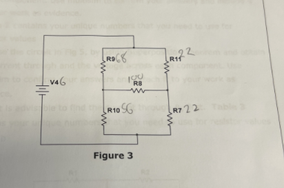
Use Thévenin’s theorem to find the current flowing through Rs in Fig.3
shown below. Use mutisim to check your answers for Rth, VT and current in Rs and include them to your work as evidence.
Task 3
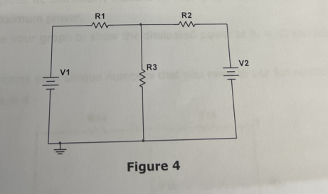
a) Analyse the circuit shown in Fig 4 by using Kirchhoff’s laws and solving simultaneous equations to obtain voltage across and current through each component. Use multisim to confirm your answers and include it to your work as evidence.
Table 2 contains your unique numbers that you need to use for resistor values
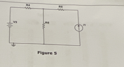
b) Analyse the circuit in Fig 5, by using Superposition Theorem and obtain
the current through and the voltage across each component. Use multisim to confirm your answers and attach it to your work as evidence.
Hint: It is advisable to find the current through R, first. Table 3 contains your unique numbers that you need to use for resistor values in part b
Task 4.
(a) State the maximum power transfer theorem
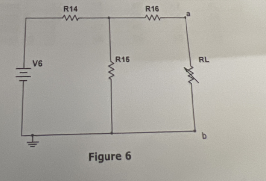
(b) For the circuit shown in Fig.6, find the Thevenin equivalent circuit to the left of terminals a-b. State the value of R, for maximum power transfer to RL
(c) Derive the formula for the power delivered to R
(d) Using suitable software and suitable values for R, plot the power against RL and clearly indicate on your graph the value of RL for maximum power.
(e) Use your graph to show the dissipated power at R1 =20 and 60.
Table 4 contains your unique numbers that you need to use for resistor values for Task 4
Are You Looking for Answer of This Assignment or Essay
Need help with your Unit 19 Electrical and Electronic Principles, Assignment 1? Our online assignment help service is here for you! We offer BTEC assignment assistance for students at an affordable price, ensuring you receive high-quality services that are 100% human-written. You can trust us to provide BTEC Level 4 Engineering Assignments Answers that will help you achieve that A+ grade. With on-time delivery guaranteed, you’ll never miss a deadline. Let our experts assist you and make your academic life easier today!
Answer