- PS954 Research Methods in Psychology Lab Report Brief 2026 | University of Essex
- MS70121E Competitive Strategy & Innovation Assessment E2 Group Report 2026
- Unit 28 Cloud Computing Assignment : The Application of Cloud Computing to an Organization
- FBU4003 Understanding Principles of Business Assignment Case Study Report
- BUSI12334 Personal and Academic Development Level 4 Assignment 1 Fashion Sustainability Report
- Leadership and Management in Adult Care Assignment Report
- 425Z0087 Quantitative Data Analysis Secondary Data Analysis Semester 1 – Report Assessment Instructions & Information
- Criminology Assignment: Investigating the Representation of Ethnicity in Media Crime Reporting Versus Official Crime Data
- D7115 Technical and Digital Leadership Assignment: A Critical Analysis of Organisational Digital Readiness, Strategic Transformation Planning, and Leadership in Enabling Digital Change
- Level 5 in Leadership and Management in Adult Care – Unit 19 Assignment : Ensuring Health and Safety Compliance and Best Practices in Adult Care Settings
- N1582 Managing Operations Assignment : Enhancing Efficiency through ITO, 4Vs, Capacity Management, and Process Mapping
- MANM376 International Finance Project Assignment: Critical Analysis of Tata Steel, Godrej Properties, and LVMH’s Strategic Financial Decisions
- AB Sugar Company Strategic Management Assignment: External, Internal, SWOT & Sustainable Growth Strategy
- Unit 3 Project Assignment Report: Planning and Delivering a Professional Training Event to Develop IT, Leadership, or Soft Skills
- CIPD 5OS05 Level 5 EDI Strategy Report: Promoting Equality, Diversity and Inclusion in Public Sector Service Organisations
- Water Resources Assignment: HEC-RAS Flow Analysis and Hydraulic Jump Evaluation in Open Channels
- HRM Reflective Assignment 1: Case Study on Strategic Growth & Employee Retention
- Qualifi Level 4 HSC401 Academic Study Skills Assignment: Portfolio on Personal Development, Source Evaluation, and Research Relevance in Health and Social Care
- AFM0ICD Budgeting Advice Assignment 1: Mr Confused Case Study on Business Budget Planning, Monitoring and Communication Using Microsoft Office Tools
- W84512A Enterprise Assignment: Business Analysis of a UK-Based SME Using Market Research, PEST & SWOT Tools BTEC Level1/Level2
H100: Determining the Capacitance of a Capacitor in an RC Circuit Engineering and Physical Sciences Foundation Programme Report , UON, UK
| University | University of Nottingham (UON) |
| Subject | H100: Engineering and Physical Sciences Foundation Programme |
Theory
The general construction of a capacitor is two conductors separated by an insulator, this enables it to store charge by building up a charge difference between the two conductors. Every capacitor
can store a certain amount of charge (Q) depending on the capacitance (C) of the capacitor and the external emf (V) charging it which give us the equation:
Q = CV [1]
When the capacitor is connected to a resistor, assuming an ideal voltage source, the time that it takes for a capacitor to become fully charged is called the time constant (τ) and it is calculated by the equation:
τ = R𝐂 [2]
Keywords
Time constant, resistor, resistance, capacitor, capacitance, Pico Scope 2000, multimeter, breadboard, series, BNC, probe, oscilloscope, signal generator.
Risk Assessment
This is a low risk experiment and in addition to the normal laboratory work rules (no shorts, no open toed shoes, bags out of the way, watching out for people around you) you will be required to cut wires.
- When cutting wires always cut away from you and downwards making sure your fingers aren’t near the sharp edges of the wire or cutters
- The edges of the wires and components will be sharp, avoid those ends
- If you do cut yourself, report this to the nearest FEPS staff member who will advise you on the next course of action after inspecting the injury
- The electrical components will have a very small current and voltage running through them so should not get hot or give you a shock. However, avoid touching them while the signal generator is connected to show good practice when working with electrical circuits
- Wash hands for 2 minutes and wear a face covering.
Equipment (video on how to set-up the experiment is on Moodle)
Pico Scope with BNC to crocodile clip connector, USB cable and oscilloscope probe A range of resistors Bi-directional ceramic capacitor of unknown capacitance Breadboard with connecting wires Multimeter with crocodile clips
Methodology
- Measure the resistance of the resistors using a multimeter and record these values with absolute uncertainties (the multimeter has a stated uncertainty of 2%)
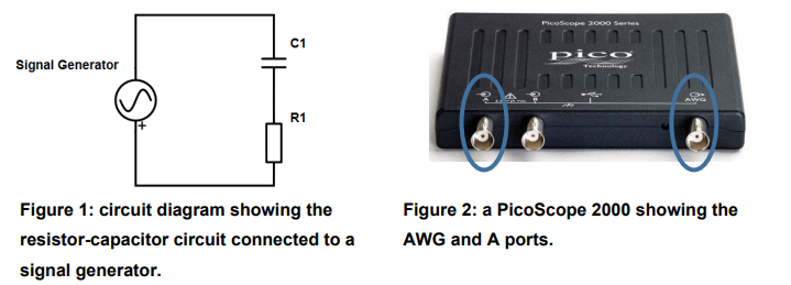
- Build the circuit, figure 1 on the breadboard, as shown in figure 3, with the capacitor and smallest resistor (take a picture of your breadboard and include this in your appendix)
- Connect the Pico Scope to the computer via the blue USB cable
- Connect the BNC to crocodile clip connector into the AWG port and the oscilloscope probe into the A port, ports
- Connect the BNC leads to the + and – on the breadboard via black and red wires
- Connect the oscilloscope probe to the wire between the capacitor and resistor and connect the earth to the black wire
- Start the Pico Scope software, switch on the signal generator, set it to square wave, 1 V and change the frequency and time base until you have about traces on the screen similar to (make sure you record this frequency)
- Set the trigger to auto and press stop
- Save this file as a pedate file with your bench number and resistor value
- Repeat steps 8 and 9 with the next resistor
- Remove the capacitor and use the LCR bridge meter to find the actual capacitance of the capacitor
- Deconstruct the circuit and Pico Scope then put everything back in its original position
- Independently process these sets of data to find the range of time constants for help), with absolute uncertainties, and draw a graph, based on equation 2, to determine the capacitance of the capacitor.
Report
This report is worth 40% of the overall mark for the PEAC module and should be written in as explained in the PEAC Laboratory Handbook on Moodle.
You are required to write an electronic report for this laboratory, to include:
- A cover sheet with contains page: module and student ID.
- A set of aims for the report to answer (about 100 words maximum)
- Tables of the measurements showing for each resistance and time constants.
- A graph of the resistance and time constant data in excel format, an annotated screen shot showing how you found the time constant for one charging and one discharging cycle of your Pico Scope trace.
- An analysis of your results (what are the trends/relationships) with reference to data
- Calculation and justification of uncertainties
- A discussion of the results. Points to include are:
a) Does your experimental capacitance value match the measured capacitance?
b) An evaluation of how your uncertainty analysis affects your results.
c) Why would you need to measure capacitance in circuits in this way? - Conclusions (which answers the aims of the experiment) and suggestions for further work
- References using IEEE (anything you had to search for should be referenced)
- Appendices (for detailed calculations and any other material that would stop the “natural flow” of the reports
Buy Answer of This Assessment & Raise Your Grades
Students Assignment Help UK offers the Best Online report writing Help in UK to college and university students who desire to score top rank in their academic careers. Our panel of subject-oriented and highly qualified writers promises to deliver a quality report on (H100) Engineering and Physical Sciences Foundation Programme for A+ Grade.
Answer