- D/618/7406 Unit 5: Challenges of IT Security in Modern Organizations – Risks, Solutions & Best Practices
- HSC Level 2/3 Unit 012 Assignment: Care Worker Responsibilities and Ways of Working
- CIPD Level 5HR03 Assignment: Understanding Reward Approaches and Their Impact on Performance and Contribution
- CIPD level 5HR02 Assignment: Talent Management and Workforce Planning Unit Guide
- Level 3 D/615/3823 Assignment: Regulation, Protection, and Collaborative Practice in Health and Social Care
- PGM216D Assignment: Bicycle Store Sales Management Application
- MATH6033 Assignment: Epidemiological Investigation of Cardiovascular Health and Tea Consumption Risks
- EH6147 Assingment: Stakeholder Analysis for Quality Improvement in Hand Hygiene Compliance
- Assignment: Investigation of Solution Concentration Through Standard Preparation, Titration, and Colorimetry Techniques
- MATH6033 Assignment: Cardiovascular Risk and Tea Drinking: Epidemiological Analyses
- CIPD level 3 3CO03 Assignment: Core behaviours for people professionals
- DAC4B1: Personal development in adult care settings
- Unit 19 Research Project Assignment 1: Impact of Corporate Social Responsibility on Business Success & Community Wellness
- EG5022 Assignment: Georeferencing and Accuracy Assessment of a Quarry 3D Model Using Photogrammetric GCPs
- Assignment: Financial Performance and Strategic Analysis of a UK Listed Company: A CORE Evaluation and Reflective Review
- 5CNMN002W Assignment: Advanced measurement- Major measurement taking off
- K/650/2298 Level 3 Understanding Roles, Responsibilities, and Effective Partnerships in Health and Social Care
- Understanding Information and Knowledge Management in the Workplace: A Briefing for HR Professionals
- HRM7010D Strategic Use of People Analytics in Enhancing Organisational Value and Agility
- TOWN1060 Urban Planning in the UK History Sustainable Design and Future City Development
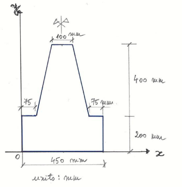
The compound cross-section shown in Figure 1a, determine the position of the Centroidwith respect to the origin of the coordinate system: Mechanical engineering Assignment, UCAS, UK
| University | Universities and Colleges Admissions Service (UCAS) |
| Subject | Mechanical Engineering |
Exercise 1:
Question 1
For the compound cross-section shown in Figure 1a, determine the position of the Centroidwith respect to the origin of the coordinate system shown in Figure 1a.
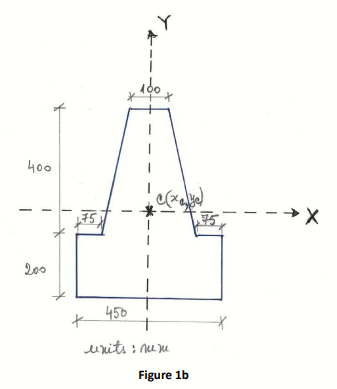
Q2 For the compound cross-section shown in Figure 1b, calculate the Second
Moment of Area of this cross-section about its horizontal axis X-X passing through the Centroid (xC, yC) determined in Q1 above.
Exercise 2:
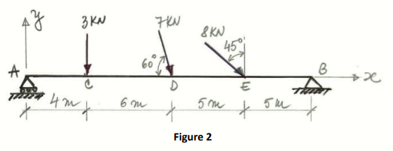
Q3 Calculate the reactions at supports for the simply supported beam subjected to the system of point forces shown in Figure 2.
Exercise 3:
Q4 For the simply supported beam shown in Figure 3, calculate the reactions at supports.
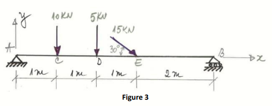
Q5 For the simply supported beam shown in Figure 3, calculate the Axial Force (N) in the beam at the sections A, C, D, E, and B shown in this figure.
Q6 Plot the Axial Force (N) diagram by using the results obtained in Q5 above.
Q7 For the simply supported beam shown in Figure 3, calculate the Shear Force (V) in the beam at the sections A, C, D, E, and B shown in this figure.
Q8 Plot the Shear Force (V) diagram by using the results obtained in Q7 above.
Q9 For the simply supported beam shown in Figure 3, calculate the Bending Moment (M) in the beam at the sections A, C, D, E, and B shown in this figure.
Q10 Plot the Bending Moment (M) diagram by using the results obtained in Q9 above.
Buy Answer of This Assessment & Raise Your Grades
Do you need someone to do my assignment? Don’t look further. At students assignment help UK we have professional experts with years of experience to craft top-rated answers on engineering assignments at a reasonable price.
