- HSC Level 2/3 Unit 012 Assignment: Care Worker Responsibilities and Ways of Working
- CIPD Level 5HR03 Assignment: Understanding Reward Approaches and Their Impact on Performance and Contribution
- CIPD level 5HR02 Assignment: Talent Management and Workforce Planning Unit Guide
- Level 3 D/615/3823 Assignment: Regulation, Protection, and Collaborative Practice in Health and Social Care
- PGM216D Assignment: Bicycle Store Sales Management Application
- MATH6033 Assignment: Epidemiological Investigation of Cardiovascular Health and Tea Consumption Risks
- EH6147 Assingment: Stakeholder Analysis for Quality Improvement in Hand Hygiene Compliance
- Assignment: Investigation of Solution Concentration Through Standard Preparation, Titration, and Colorimetry Techniques
- MATH6033 Assignment: Cardiovascular Risk and Tea Drinking: Epidemiological Analyses
- CIPD level 3 3CO03 Assignment: Core behaviours for people professionals
- DAC4B1: Personal development in adult care settings
- Unit 19 Research Project Assignment 1: Impact of Corporate Social Responsibility on Business Success & Community Wellness
- EG5022 Assignment: Georeferencing and Accuracy Assessment of a Quarry 3D Model Using Photogrammetric GCPs
- Assignment: Financial Performance and Strategic Analysis of a UK Listed Company: A CORE Evaluation and Reflective Review
- 5CNMN002W Assignment: Advanced measurement- Major measurement taking off
- K/650/2298 Level 3 Understanding Roles, Responsibilities, and Effective Partnerships in Health and Social Care
- Understanding Information and Knowledge Management in the Workplace: A Briefing for HR Professionals
- HRM7010D Strategic Use of People Analytics in Enhancing Organisational Value and Agility
- TOWN1060 Urban Planning in the UK History Sustainable Design and Future City Development
- OTHM Level 5: J/650/1143 Research Methods in Health and Social Care
Truth table (Table 1) for a Four-Input digital system is shown below: Electronic Systems, Assignment, LU, UK
| University | Loughborough University (LU) |
| Subject | Electronic Systems |
1.
a) Truth table (Table 1) for a Four-Input digital system is shown below.
Table 1
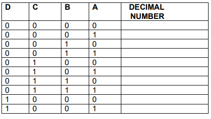
i. Using the variable A to represent the 20 digital input, B for 21, C for 22, and D for 23 identify all the possible combinations that produce an even number.
ii. Write down a Boolean expression that will output a HIGH (1) whenever the 4-bit binary input is an even number from Table 1.
iii. Simplify all the above expressions into its simplest form by using a Karnaugh map.
iv. Draw the logic circuit diagram that could be used to represent the simplified Boolean expression in (iii).
Do You Need Assignment of This Question
b) Given a combinational logic circuit shown in Figure Q1b below:-
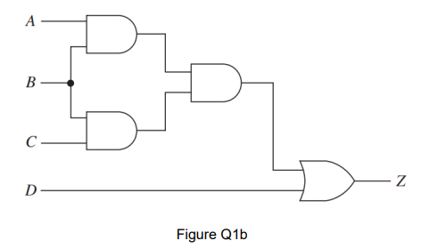
i. Derive the equation that will produce the output waveform at Z.
ii. Using Boolean algebra, simplify the equation in (i).
iii. Draw the logic circuit for this simplified equation.
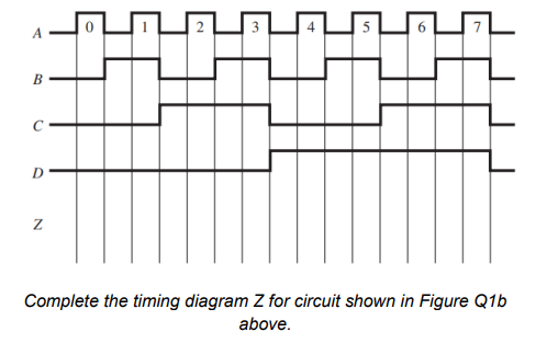
iv. Complete the timing diagram Z for the combinational logic
circuit shown in Figure Q1b.
Buy Answer of This Assessment & Raise Your Grades
2.
a) The logic circuit shown in Figure Q2a is implemented to produce an output at X based on the input conditions at A, B, C and D.
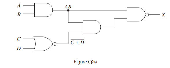
i. Derive the Boolean equation at X.
ii. Use De Morgan’s theorem and then Boolean algebra to simplify the Boolean equation.
iii. Draw the simplified logic circuit.
b) Figure Q2b shows a network of three DC supplies and three resistances. I3 is known to equal 1.5 A. Find the value of I1, I2 and unknown resistance, R.
Find the following values of
i. I1
ii. I2
iii. unknown resistance, R.

c) Figure Q2c shows a typical transformer and rectifier circuit.

i. What is the open circuit output voltage for the following transformer and rectifier circuit if the input voltage across the primary winding is 110V 50Hz and the primary winding has 1000 turns, whilst the secondary winding has 260 turns?
ii. Draw the output waveform and indicate the peak magnitude of the output voltage.
Are You Looking for Answer of This Assignment or Essay
Tackling an electronic systems assignment can be challenging, but you don’t have to do it alone! Our comprehensive assignment assistance online is here to make your life easier. If you’re feeling overwhelmed, just pay someone to do my assignment, and our skilled experts will handle it with expertise. Additionally, our homework writing helper in UK is available to provide personalized guidance and support. Take control of your studies and let us help you achieve the grades you aim for!
Answer