- UGB394 Assignment: Strategic Evaluation and Reporting in International Financial Accounting
- Wrong Site Surgery Case Study: Investigation, Causes & Prevention – Report
- MANM013 Strategic Internationalisation Report – Market Entry Analysis & Trade Strategy, FHEQ Level 7
- IMA7001 International Marketing Strategy Report for Gousto Expansion into Australia and Canada, Level HE7 Assessment 1
- CMI 526 Principles of Leadership Practice Level 5 – Report
- H/618/5284 Responsibilities of a Health and Social Care Worker, OTHM Level 3
- BTEC M/618/7393 Unit 2: Principles and Design of Networked Systems – Report
- 6005FIN Portfolio Management Report – Risk-Reduction Benefits of Diversification
- 2190 Level 4 Address various Legal , social & Ethical issues within cyber security – Report
- BEAM046 Investment Strategies for University of Exeter: Bond & crypto portfolio Analysis
- CIPD 7OS01 level 7 Legal Risks in Employment Decisions at Rose Hip Lodge – A detailed Analysis
- UGB394 International Financial Reporting – Analysis, Statements & Decision-Making, Level 6
- R/616/1790 Unit 3: Review of Professional Identity and Practice, BTEC Level 4
- Y/616/1788 Unit 1: The Contemporary Hospitality Industry, BTEC Level 4
- OTHM Level 3 Communication in the Workplace: Strategies, Challenges, and Best Practices | Report
- Financial Management Strategies of MNCs: Global Capital Sourcing, Currency Exposure, and Cost of Capital
- ECM2201 SDOF & MDOF System Analysis Report
- EMS622U Sustainability Assessment for Product Design: Environmental, Economic, and Social Indicators | Report
- M33984 International Marketing Plan | Report, Assessment 2
- D/615/3823 Roles & Responsibilities in Health and Social Care, Qualifi Level 3
Unit 24 Structural Analysis Report – Pearson BTEC Level 3 Engineering – Simply Supported & Cantilever Beams
| University | Pearson BTEC |
You need to produce a report that demonstrates analytical and practical skills and use these to explain the effects of loads on simply supported and cantilever beams, suggesting improvements to the structures.
Task 1A:
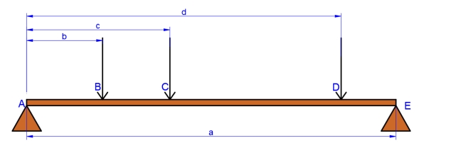
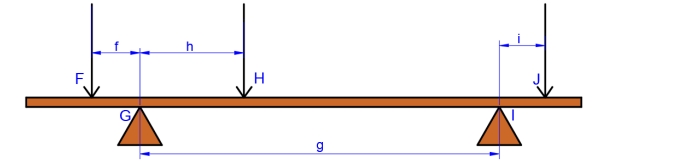
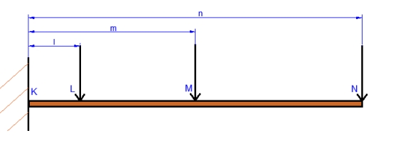
Below are diagrams that show two simply supported beams and a cantilever beam, each of which has three point loads. You need to:
● Create a mathematical model of the shear force and bending moments for each beam arrangement, For each you need to present your findings as annotated shear force and bending moment diagrams.
● Create a mathematical model for the maximum deflection on the Cantilever
beam
● Use your diagrams to identify significant data, including maximum and minimum values, points of contraflexure and the Shear force and bending moment values at the halfway section of the simply supported beams
● Safely set up apparatus for each beam arrangement using the distance and
loading given to you. Once set up, you need to gather experimental results for
each beam. To include; reaction forces at the supports, Shear force and
bending moment values at the halfway section of the simply supported beams
and the maximum deflection of the cantilever beams
● Record all your work in the Logbook template provided. Your logbook must be neat, tidy and well presented as a professional document.
Find your individual data for the distances and forces in the data sheets provided.
Note: The force asserted by the mass of the beam is to be ignored.
Take Gravity as : 9.81 m/s2
Task 1A- beam A1: (Note: diagram is not to scale)
Task 1A- beam A2: (Note: diagram is not to scale)
Task 1A- beam A3: (Note: diagram is not to scale)
● Modulus of Elasticity for Mild steel: 2×10⁵ N/mm2
● Area moment of Inertia for 16 x16 mm square section beam: 5.461×103 mm4
Do You Need Assignment of This Question
Task 1B
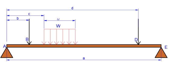
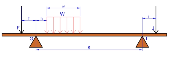
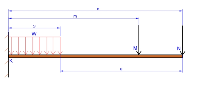
Below are diagrams that show two simply supported beams and a cantilever beam, each of which has two point loads and an UDL. You need to:
● Create a mathematical model of the shear force and bending moments for each beam arrangement, For each you need to present your findings as annotated shear force and bending moment diagrams.
● Create a mathematical model for the maximum deflection on the Cantilever
beam
● Use your diagrams to identify significant data, including maximum and minimum values, points of contraflexure and the Shear force and bending moment values at the halfway section of the simply supported beams
● Safely set up apparatus for each beam arrangement using the distance and
loading given to you. Once set up, you need to gather experimental results for
each beam. To include; reaction forces at the supports, Shear force and
bending moment values at the halfway section of the simply supported beams
and the maximum deflection of the cantilever beams
● Record all your work in the Logbook template provided. Your logbook must be neat, tidy and presented well as a professional document.
Find your individual data for the distances and forces in the data sheets provided.
Note: The force asserted by the mass of the beam is to be ignored.
Take Gravity as : 9.81 m/s2
Task 1B- beam B1: (Note: diagram is not to scale)
Task 1B- beam B2: (Note: diagram is not to scale)
Task 1B- beam B3: (Note: diagram is not to scale)
● Modulus of Elasticity for Mild steel: 2×10⁵ N/mm2
● Area moment of Inertia for 16 x16 mm square section beam: 5.461×103 mm4
Buy Answer of This Assessment & Raise Your Grades
Answer